Polypipe Red Floor Panel 1200mm × 1000mm | Screeded UFH Floor System | PB08576
PB08576 Red Floor Panel 1200mm × 1000mm Solid / Screeded Floors
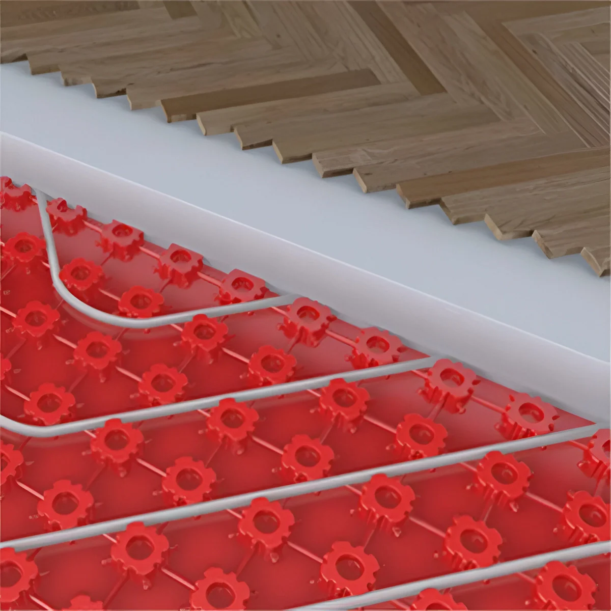
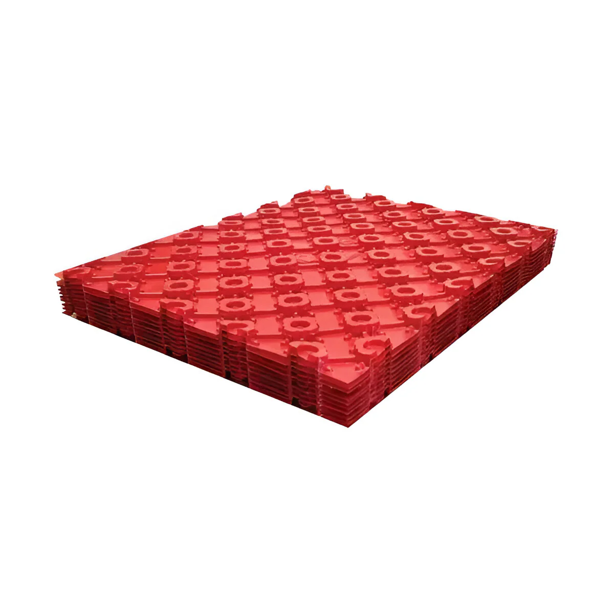
The Polypipe Red Floor Panel (PB08576) is the optimum-performance pipe positioning and guide panel for water underfloor heating in new-build and renovation solid or screeded floors. Each 1200mm × 1000mm lightweight plastic panel forms an interlocking castellated grid that guides 15mm or 18mm UFH pipe into precise spacing configurations — 100mm, 200mm, or 300mm centres — while elevating the pipe slightly off the insulation so it becomes fully embedded in screed for maximum heat output. Panels nest together for storage and site handling, and offer a degree of protection to laid pipework while other trades continue working before screeding. Allow for overlap and waste when calculating quantities.
Why Use the Polypipe Red Panel System?
The Polypipe Red Floor Panel system is one of two solid floor installation methods Polypipe offers — the other being the Clip Rail system. While the Clip Rail uses separate rails to position the pipe, the Red Panel provides a complete pre-formed grid that the pipe is guided through directly. The castellated knobs in the panel surface grip and hold the pipe at the pre-determined spacing, eliminating the need for separate clips, measuring, or chalked guidelines. The result is faster, more consistent pipe spacing — particularly beneficial for spiral (snail) configurations where precise, even spacing is important for uniform heat distribution.
A key performance advantage of the red panel system is that the castellated surface lifts the pipe slightly above the insulation boards beneath. This allows screed to flow underneath the pipe as well as above it, fully enveloping the pipe in the screed mass. Full pipe encapsulation improves heat transfer between the heated water and the screed, and increases the thermal mass effect of the system. Additionally, once screeded, the panels displace approximately 15% of the screed volume, slightly reducing the amount of screed material needed.
Key Features & Benefits
Performance Data
| Pipe Spacing | Heat Output (50°C flow temp) | Max Coverage per Circuit | Pipe Required |
|---|---|---|---|
| 100mm centres | Approx 91 W/m² | 12m² (15mm pipe) | 8.2m per m² |
| 200mm centres | Approx 91 W/m² at 50°C | 22m² (15mm or 18mm pipe) | 4.5m per m² |
| 300mm centres | Lower output | 30m² (18mm pipe only) | 3.3m per m² |
Maximum circuit length: 100m for all pipe sizes. Allow for connection tails (manifold to floor and return) when calculating net floor coverage per circuit. For 12m pipe (Overlay system), use the Overlay™ panel range — these red panels are for 15mm and 18mm pipe in solid/screeded floor applications.
Compatible Floor Constructions
- Sand and cement screed (traditional)
- Pumped liquid screed (anhydrite / calcium sulphate)
- Fine concrete and heavy concrete
- Polymer modified screeds
Panels are laid over pre-installed rigid insulation boards (not included). Optimum screed depth is 65mm measured from the base of the panel — equivalent to approximately 40mm of screed above the top of the pipe. This gives the best balance of thermal mass and heat-up time.
Technical Specifications
| Specification | Detail |
|---|---|
| MPN | PB08576 |
| Brand | Polypipe |
| Panel dimensions | 1200mm × 1000mm |
| Coverage per panel | 1.2m² (actual); allow for overlap and waste |
| Material | Lightweight plastic (polypropylene) |
| Colour | Red |
| Compatible pipe sizes | 15mm and 18mm UFH barrier pipe |
| Pipe centres available | 100mm, 200mm, 300mm (18mm pipe) |
| Maximum circuit length | 100m |
| Optimum screed depth | 65mm from panel base (40mm above pipe top) |
| Heat output (50°C, 200mm) | Approx 91 W/m² |
| Screed volume displaced | Approx 15% (reduces screed material required) |
| Panel joints | Interlocking (½ castellation over ¾ castellation) |
| Application | Solid / screeded floors — new build and renovation |
Installation Guide
Install insulation boards to the required depth across the entire floor area first. Lay the first red floor panel with the ½-castellation edge against the wall. Interlock subsequent panels — the ½-castellation of each panel overlaps the ¾-castellation of the previous. Continue to fill the room, cutting panels to fit at perimeter edges and around obstacles. Fit edge expansion strip around the room perimeter before laying pipe — this accommodates thermal expansion of the screed. Lay pipe from the outside of the coil, unrolling in the direction of travel. For spiral configurations, route the pipe through the castellations at the required spacing, using two castellations for a 90° bend and three for a 180°. Secure at bends and circuit ends with PB02911 pipe clips. Connect circuit tails to the manifold using conduit pipe (CPC1525 or CPC2225) to protect the pipe through the screed perimeter. Have the screed contractor pour after system pressure testing — leave the system pressurised during screeding to reveal any accidental damage. Optimum screed depth: 65mm from panel base.
⚠️ Ordering — Allow for Overlap and Waste
Each panel covers 1.2m² actual area, but the interlocking joints and perimeter cuts will consume additional panels. As a general rule, add 10–15% to the calculated floor area when ordering. For example, a 20m² room will require a minimum of 17 panels (20 ÷ 1.2 = 16.7), but ordering 19–20 is recommended to allow for cuts and waste. Contact us if you need help calculating quantities for your project.
Frequently Asked Questions
Can I use these panels with 12mm pipe?
No. The PB08576 red floor panels are designed for 15mm and 18mm barrier pipe. For 12mm pipe installations — such as the Polypipe Overlay system — use the Overlay™ floor panel range (PB08570 / PB08571), which has grooves sized for 12mm pipe. Using 12mm pipe in the PB08576 castellations would not secure the pipe correctly or maintain the minimum bend radius.
Do the panels need to be fixed to the insulation?
The panels sit on the insulation boards and are held in position by the weight of the screed and the interlocking panel joints. In most installations, no additional fixing of the panels to the insulation is required — the pipe tensioning and serpentine routing holds the panels flat. In sloping or uneven areas, panels can be temporarily secured with tape or nails through the insulation.
What insulation do I need under the panels?
Polypipe recommends rigid insulation boards under the red panel system — typically EPS (expanded polystyrene) or PIR boards of adequate thickness for the floor application. The required insulation thickness depends on the floor type (ground floor, intermediate floor, over unheated space), the building's U-value target, and local Building Regulations requirements. A minimum of 50mm EPS is typical for ground floors; consult your UFH designer or Building Control for the specific requirement for your project.
Can I use the panels with both spiral and serpentine layouts?
Yes — the red panel system supports both spiral (snail) and serpentine (boustrophedon) pipe layouts. Polypipe recommends the spiral configuration where possible, as it produces more even temperature distribution across the floor — each circuit has both the flow and return legs interleaved, preventing distinct hot and cool zones. The serpentine layout is simpler but results in a temperature gradient from flow end to return end of the circuit.
Original: $36.44
-65%$36.44
$12.75More Images
Polypipe Red Floor Panel 1200mm × 1000mm | Screeded UFH Floor System | PB08576
PB08576 Red Floor Panel 1200mm × 1000mm Solid / Screeded Floors
The Polypipe Red Floor Panel (PB08576) is the optimum-performance pipe positioning and guide panel for water underfloor heating in new-build and renovation solid or screeded floors. Each 1200mm × 1000mm lightweight plastic panel forms an interlocking castellated grid that guides 15mm or 18mm UFH pipe into precise spacing configurations — 100mm, 200mm, or 300mm centres — while elevating the pipe slightly off the insulation so it becomes fully embedded in screed for maximum heat output. Panels nest together for storage and site handling, and offer a degree of protection to laid pipework while other trades continue working before screeding. Allow for overlap and waste when calculating quantities.
Why Use the Polypipe Red Panel System?
The Polypipe Red Floor Panel system is one of two solid floor installation methods Polypipe offers — the other being the Clip Rail system. While the Clip Rail uses separate rails to position the pipe, the Red Panel provides a complete pre-formed grid that the pipe is guided through directly. The castellated knobs in the panel surface grip and hold the pipe at the pre-determined spacing, eliminating the need for separate clips, measuring, or chalked guidelines. The result is faster, more consistent pipe spacing — particularly beneficial for spiral (snail) configurations where precise, even spacing is important for uniform heat distribution.
A key performance advantage of the red panel system is that the castellated surface lifts the pipe slightly above the insulation boards beneath. This allows screed to flow underneath the pipe as well as above it, fully enveloping the pipe in the screed mass. Full pipe encapsulation improves heat transfer between the heated water and the screed, and increases the thermal mass effect of the system. Additionally, once screeded, the panels displace approximately 15% of the screed volume, slightly reducing the amount of screed material needed.
Key Features & Benefits
Performance Data
| Pipe Spacing | Heat Output (50°C flow temp) | Max Coverage per Circuit | Pipe Required |
|---|---|---|---|
| 100mm centres | Approx 91 W/m² | 12m² (15mm pipe) | 8.2m per m² |
| 200mm centres | Approx 91 W/m² at 50°C | 22m² (15mm or 18mm pipe) | 4.5m per m² |
| 300mm centres | Lower output | 30m² (18mm pipe only) | 3.3m per m² |
Maximum circuit length: 100m for all pipe sizes. Allow for connection tails (manifold to floor and return) when calculating net floor coverage per circuit. For 12m pipe (Overlay system), use the Overlay™ panel range — these red panels are for 15mm and 18mm pipe in solid/screeded floor applications.
Compatible Floor Constructions
- Sand and cement screed (traditional)
- Pumped liquid screed (anhydrite / calcium sulphate)
- Fine concrete and heavy concrete
- Polymer modified screeds
Panels are laid over pre-installed rigid insulation boards (not included). Optimum screed depth is 65mm measured from the base of the panel — equivalent to approximately 40mm of screed above the top of the pipe. This gives the best balance of thermal mass and heat-up time.
Technical Specifications
| Specification | Detail |
|---|---|
| MPN | PB08576 |
| Brand | Polypipe |
| Panel dimensions | 1200mm × 1000mm |
| Coverage per panel | 1.2m² (actual); allow for overlap and waste |
| Material | Lightweight plastic (polypropylene) |
| Colour | Red |
| Compatible pipe sizes | 15mm and 18mm UFH barrier pipe |
| Pipe centres available | 100mm, 200mm, 300mm (18mm pipe) |
| Maximum circuit length | 100m |
| Optimum screed depth | 65mm from panel base (40mm above pipe top) |
| Heat output (50°C, 200mm) | Approx 91 W/m² |
| Screed volume displaced | Approx 15% (reduces screed material required) |
| Panel joints | Interlocking (½ castellation over ¾ castellation) |
| Application | Solid / screeded floors — new build and renovation |
Installation Guide
Install insulation boards to the required depth across the entire floor area first. Lay the first red floor panel with the ½-castellation edge against the wall. Interlock subsequent panels — the ½-castellation of each panel overlaps the ¾-castellation of the previous. Continue to fill the room, cutting panels to fit at perimeter edges and around obstacles. Fit edge expansion strip around the room perimeter before laying pipe — this accommodates thermal expansion of the screed. Lay pipe from the outside of the coil, unrolling in the direction of travel. For spiral configurations, route the pipe through the castellations at the required spacing, using two castellations for a 90° bend and three for a 180°. Secure at bends and circuit ends with PB02911 pipe clips. Connect circuit tails to the manifold using conduit pipe (CPC1525 or CPC2225) to protect the pipe through the screed perimeter. Have the screed contractor pour after system pressure testing — leave the system pressurised during screeding to reveal any accidental damage. Optimum screed depth: 65mm from panel base.
⚠️ Ordering — Allow for Overlap and Waste
Each panel covers 1.2m² actual area, but the interlocking joints and perimeter cuts will consume additional panels. As a general rule, add 10–15% to the calculated floor area when ordering. For example, a 20m² room will require a minimum of 17 panels (20 ÷ 1.2 = 16.7), but ordering 19–20 is recommended to allow for cuts and waste. Contact us if you need help calculating quantities for your project.
Frequently Asked Questions
Can I use these panels with 12mm pipe?
No. The PB08576 red floor panels are designed for 15mm and 18mm barrier pipe. For 12mm pipe installations — such as the Polypipe Overlay system — use the Overlay™ floor panel range (PB08570 / PB08571), which has grooves sized for 12mm pipe. Using 12mm pipe in the PB08576 castellations would not secure the pipe correctly or maintain the minimum bend radius.
Do the panels need to be fixed to the insulation?
The panels sit on the insulation boards and are held in position by the weight of the screed and the interlocking panel joints. In most installations, no additional fixing of the panels to the insulation is required — the pipe tensioning and serpentine routing holds the panels flat. In sloping or uneven areas, panels can be temporarily secured with tape or nails through the insulation.
What insulation do I need under the panels?
Polypipe recommends rigid insulation boards under the red panel system — typically EPS (expanded polystyrene) or PIR boards of adequate thickness for the floor application. The required insulation thickness depends on the floor type (ground floor, intermediate floor, over unheated space), the building's U-value target, and local Building Regulations requirements. A minimum of 50mm EPS is typical for ground floors; consult your UFH designer or Building Control for the specific requirement for your project.
Can I use the panels with both spiral and serpentine layouts?
Yes — the red panel system supports both spiral (snail) and serpentine (boustrophedon) pipe layouts. Polypipe recommends the spiral configuration where possible, as it produces more even temperature distribution across the floor — each circuit has both the flow and return legs interleaved, preventing distinct hot and cool zones. The serpentine layout is simpler but results in a temperature gradient from flow end to return end of the circuit.
Product Information
Product Information
Shipping & Returns
Shipping & Returns
Description
PB08576 Red Floor Panel 1200mm × 1000mm Solid / Screeded Floors
The Polypipe Red Floor Panel (PB08576) is the optimum-performance pipe positioning and guide panel for water underfloor heating in new-build and renovation solid or screeded floors. Each 1200mm × 1000mm lightweight plastic panel forms an interlocking castellated grid that guides 15mm or 18mm UFH pipe into precise spacing configurations — 100mm, 200mm, or 300mm centres — while elevating the pipe slightly off the insulation so it becomes fully embedded in screed for maximum heat output. Panels nest together for storage and site handling, and offer a degree of protection to laid pipework while other trades continue working before screeding. Allow for overlap and waste when calculating quantities.
Why Use the Polypipe Red Panel System?
The Polypipe Red Floor Panel system is one of two solid floor installation methods Polypipe offers — the other being the Clip Rail system. While the Clip Rail uses separate rails to position the pipe, the Red Panel provides a complete pre-formed grid that the pipe is guided through directly. The castellated knobs in the panel surface grip and hold the pipe at the pre-determined spacing, eliminating the need for separate clips, measuring, or chalked guidelines. The result is faster, more consistent pipe spacing — particularly beneficial for spiral (snail) configurations where precise, even spacing is important for uniform heat distribution.
A key performance advantage of the red panel system is that the castellated surface lifts the pipe slightly above the insulation boards beneath. This allows screed to flow underneath the pipe as well as above it, fully enveloping the pipe in the screed mass. Full pipe encapsulation improves heat transfer between the heated water and the screed, and increases the thermal mass effect of the system. Additionally, once screeded, the panels displace approximately 15% of the screed volume, slightly reducing the amount of screed material needed.
Key Features & Benefits
Performance Data
| Pipe Spacing | Heat Output (50°C flow temp) | Max Coverage per Circuit | Pipe Required |
|---|---|---|---|
| 100mm centres | Approx 91 W/m² | 12m² (15mm pipe) | 8.2m per m² |
| 200mm centres | Approx 91 W/m² at 50°C | 22m² (15mm or 18mm pipe) | 4.5m per m² |
| 300mm centres | Lower output | 30m² (18mm pipe only) | 3.3m per m² |
Maximum circuit length: 100m for all pipe sizes. Allow for connection tails (manifold to floor and return) when calculating net floor coverage per circuit. For 12m pipe (Overlay system), use the Overlay™ panel range — these red panels are for 15mm and 18mm pipe in solid/screeded floor applications.
Compatible Floor Constructions
- Sand and cement screed (traditional)
- Pumped liquid screed (anhydrite / calcium sulphate)
- Fine concrete and heavy concrete
- Polymer modified screeds
Panels are laid over pre-installed rigid insulation boards (not included). Optimum screed depth is 65mm measured from the base of the panel — equivalent to approximately 40mm of screed above the top of the pipe. This gives the best balance of thermal mass and heat-up time.
Technical Specifications
| Specification | Detail |
|---|---|
| MPN | PB08576 |
| Brand | Polypipe |
| Panel dimensions | 1200mm × 1000mm |
| Coverage per panel | 1.2m² (actual); allow for overlap and waste |
| Material | Lightweight plastic (polypropylene) |
| Colour | Red |
| Compatible pipe sizes | 15mm and 18mm UFH barrier pipe |
| Pipe centres available | 100mm, 200mm, 300mm (18mm pipe) |
| Maximum circuit length | 100m |
| Optimum screed depth | 65mm from panel base (40mm above pipe top) |
| Heat output (50°C, 200mm) | Approx 91 W/m² |
| Screed volume displaced | Approx 15% (reduces screed material required) |
| Panel joints | Interlocking (½ castellation over ¾ castellation) |
| Application | Solid / screeded floors — new build and renovation |
Installation Guide
Install insulation boards to the required depth across the entire floor area first. Lay the first red floor panel with the ½-castellation edge against the wall. Interlock subsequent panels — the ½-castellation of each panel overlaps the ¾-castellation of the previous. Continue to fill the room, cutting panels to fit at perimeter edges and around obstacles. Fit edge expansion strip around the room perimeter before laying pipe — this accommodates thermal expansion of the screed. Lay pipe from the outside of the coil, unrolling in the direction of travel. For spiral configurations, route the pipe through the castellations at the required spacing, using two castellations for a 90° bend and three for a 180°. Secure at bends and circuit ends with PB02911 pipe clips. Connect circuit tails to the manifold using conduit pipe (CPC1525 or CPC2225) to protect the pipe through the screed perimeter. Have the screed contractor pour after system pressure testing — leave the system pressurised during screeding to reveal any accidental damage. Optimum screed depth: 65mm from panel base.
⚠️ Ordering — Allow for Overlap and Waste
Each panel covers 1.2m² actual area, but the interlocking joints and perimeter cuts will consume additional panels. As a general rule, add 10–15% to the calculated floor area when ordering. For example, a 20m² room will require a minimum of 17 panels (20 ÷ 1.2 = 16.7), but ordering 19–20 is recommended to allow for cuts and waste. Contact us if you need help calculating quantities for your project.
Frequently Asked Questions
Can I use these panels with 12mm pipe?
No. The PB08576 red floor panels are designed for 15mm and 18mm barrier pipe. For 12mm pipe installations — such as the Polypipe Overlay system — use the Overlay™ floor panel range (PB08570 / PB08571), which has grooves sized for 12mm pipe. Using 12mm pipe in the PB08576 castellations would not secure the pipe correctly or maintain the minimum bend radius.
Do the panels need to be fixed to the insulation?
The panels sit on the insulation boards and are held in position by the weight of the screed and the interlocking panel joints. In most installations, no additional fixing of the panels to the insulation is required — the pipe tensioning and serpentine routing holds the panels flat. In sloping or uneven areas, panels can be temporarily secured with tape or nails through the insulation.
What insulation do I need under the panels?
Polypipe recommends rigid insulation boards under the red panel system — typically EPS (expanded polystyrene) or PIR boards of adequate thickness for the floor application. The required insulation thickness depends on the floor type (ground floor, intermediate floor, over unheated space), the building's U-value target, and local Building Regulations requirements. A minimum of 50mm EPS is typical for ground floors; consult your UFH designer or Building Control for the specific requirement for your project.
Can I use the panels with both spiral and serpentine layouts?
Yes — the red panel system supports both spiral (snail) and serpentine (boustrophedon) pipe layouts. Polypipe recommends the spiral configuration where possible, as it produces more even temperature distribution across the floor — each circuit has both the flow and return legs interleaved, preventing distinct hot and cool zones. The serpentine layout is simpler but results in a temperature gradient from flow end to return end of the circuit.