
SolarEdge 230/400V Energy Meter with Modbus Connection
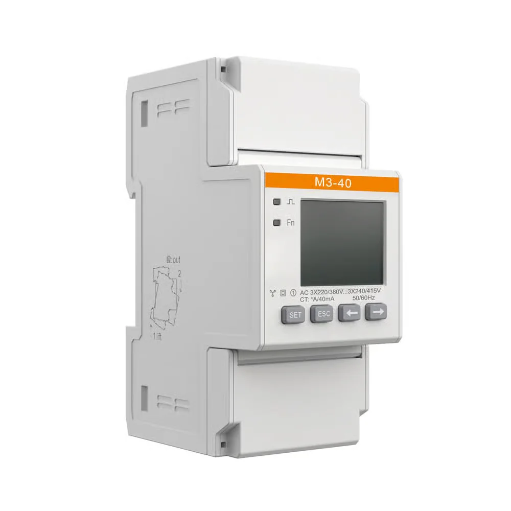
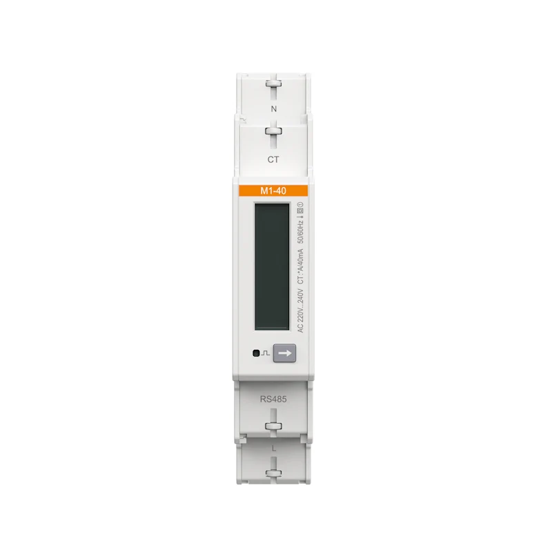
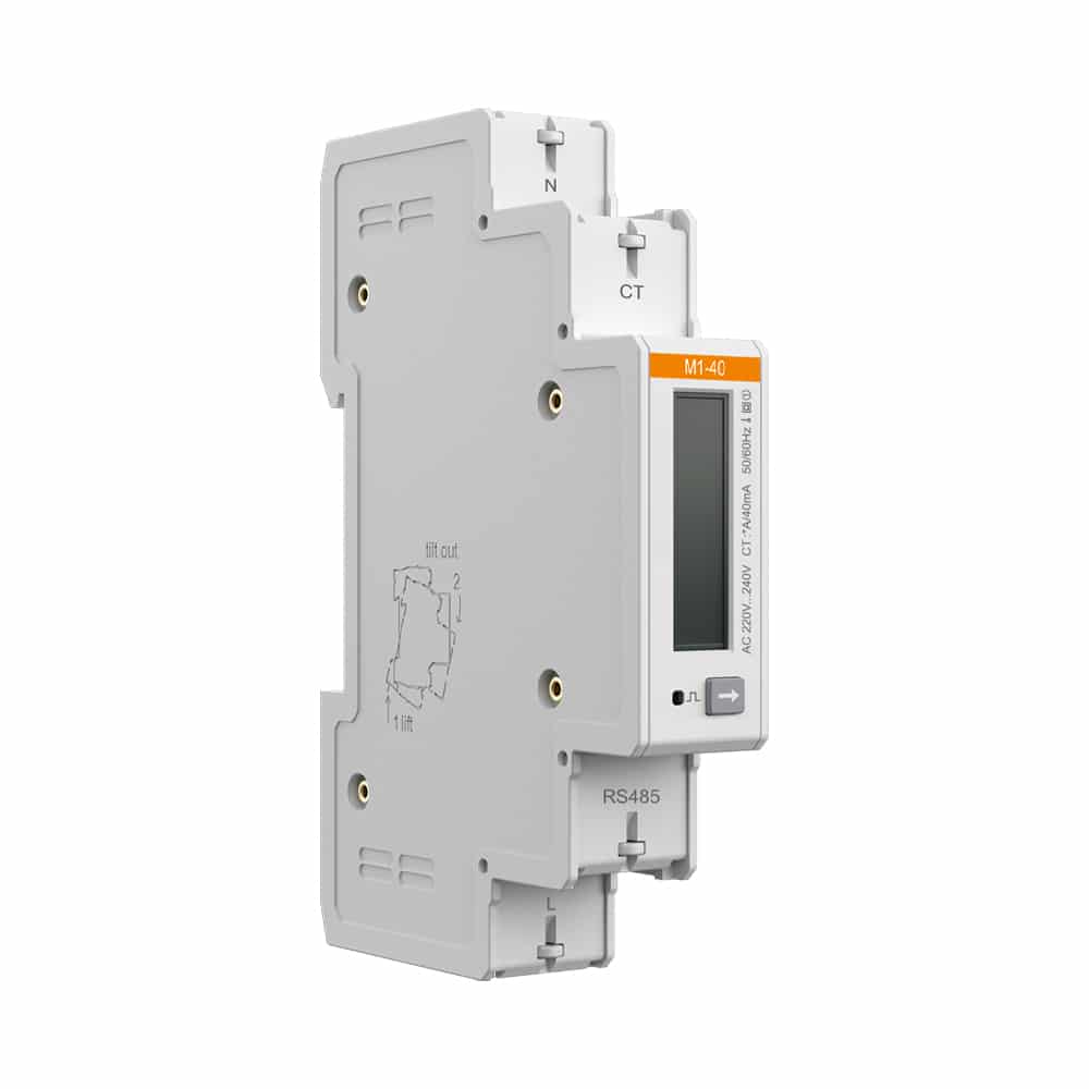
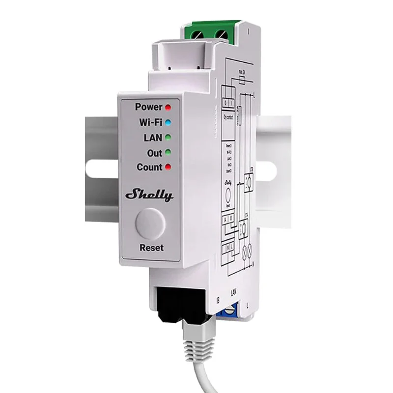
The SolarEdge SE-WND-3Y400-MB-K2 is SolarEdge's dedicated Modbus energy meter for accurate production, consumption, and import/export monitoring in both single-phase and three-phase solar PV installations. It connects to any SolarEdge inverter or Control and Communication Gateway via RS485 Modbus, enabling real-time energy flow data in the SolarEdge monitoring platform. The K2 version is required for export limitation (G100) — it supports Engineering Recommendation G100 Issue 1 Amendment 1 2017 and is the version specified by DNOs for feed-in control in the UK. Compact DIN-rail mounting and a 5-year warranty make it a standard inclusion on any SolarEdge installation.
| Manufacturer | SolarEdge Technologies |
| Part Number | SE-WND-3Y400-MB-K2 |
| Nominal Voltage — Line to Neutral | 230 Vac |
| Nominal Voltage — Line to Line | 400 Vac |
| Operating Voltage Range | 184–264 Vac (L-N) / 320–460 Vac (L-L) |
| AC Frequency | 48–62 Hz |
| Grids Supported | Single phase (L / N / PE) & three phase (L1 / L2 / L3 / N / PE) |
| Power Consumption | 1.8 W (typical) |
| Communication Interface | RS485 Modbus |
| Response Time | ≤ 1 second |
| Default Modbus Device ID | 2 |
| RS485 Line Termination | 120 Ω |
| Accuracy (@ 25°C, PF: 1) | ±1.0% across 1%–100% of rated CT current |
| Dimensions (H × W × D) | 85 × 153 × 38 mm |
| Weight | 310 g |
| Enclosure | High-impact ABS / ABS-PC plastic, UL 94V-0 / IEC FV-0 |
| Mounting | DIN rail or wall mount |
| Operating Temperature | –40°C to +75°C |
| Relative Humidity | 5–90% (non-condensing) |
| Protection Rating | Indoor; outdoor when installed in a suitable outdoor enclosure |
| Export Limitation Standard | Engineering Recommendation G100 Issue 1 Amendment 1 2017 (ENA, UK) |
| Safety Standard | IEC 61010-1 (3rd Edition) |
| Emissions | FCC Part 15 Class B, CISPR11:2009 Class B |
| Wiring — AC | 1.3–2.0 mm diameter (16–12 AWG), 600 V stranded |
| Wiring — RS485 | Min. 3-wire shielded twisted pair, 0.2–1 mm² (24–18 AWG); CAT5 acceptable |
| Warranty | 5 years |
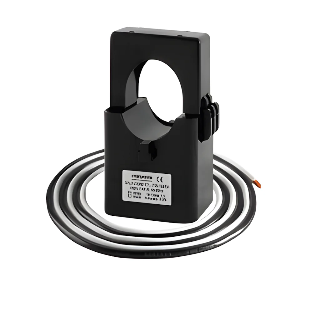
| Model | Rated RMS Current | Internal / External Dimensions |
|---|---|---|
| SECT-SPL-100A-A | 100 A | 16 × 16 mm / 44 × 31 mm |
| SECT-SPL-250A-A | 250 A | 24 × 25 mm / 46.2 × 65.4 mm |
| SECT-SPL-1000A-A | 1000 A | 52 × 52 mm / 120 × 125 mm |
Why is the K2 version required for export limitation?
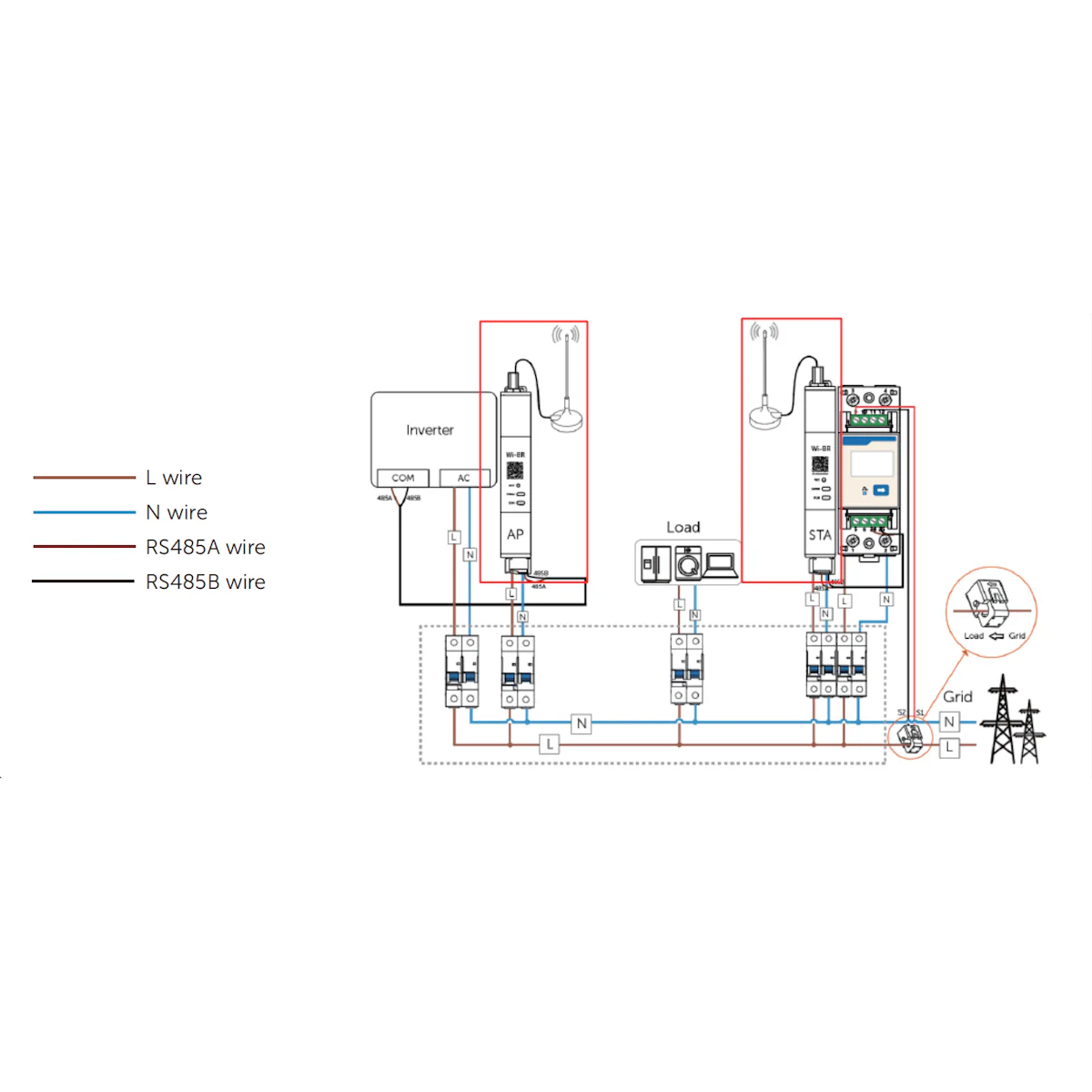
Where is the meter installed — grid side or inverter side?
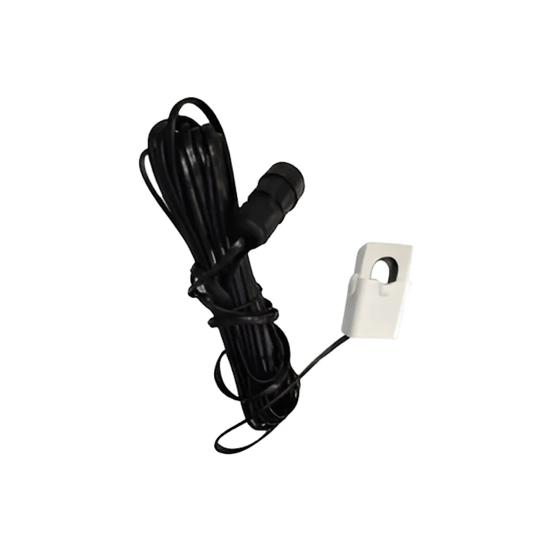
Which CT rating should I choose?
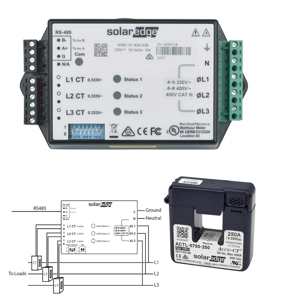
How does the meter connect to the SolarEdge inverter?
Original: $201.10
-65%$201.10
$70.38More Images
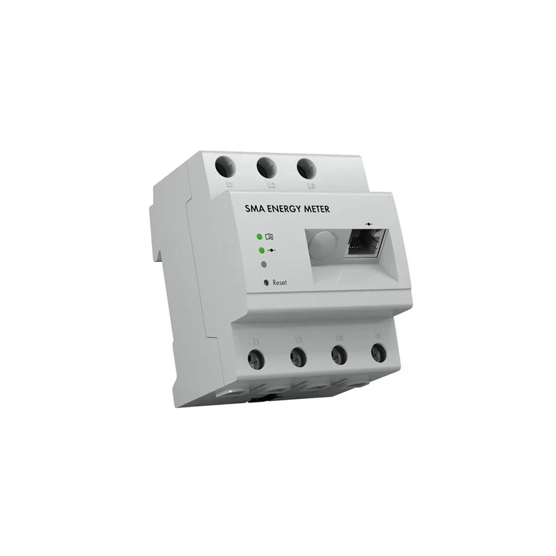
SolarEdge 230/400V Energy Meter with Modbus Connection
The SolarEdge SE-WND-3Y400-MB-K2 is SolarEdge's dedicated Modbus energy meter for accurate production, consumption, and import/export monitoring in both single-phase and three-phase solar PV installations. It connects to any SolarEdge inverter or Control and Communication Gateway via RS485 Modbus, enabling real-time energy flow data in the SolarEdge monitoring platform. The K2 version is required for export limitation (G100) — it supports Engineering Recommendation G100 Issue 1 Amendment 1 2017 and is the version specified by DNOs for feed-in control in the UK. Compact DIN-rail mounting and a 5-year warranty make it a standard inclusion on any SolarEdge installation.
| Manufacturer | SolarEdge Technologies |
| Part Number | SE-WND-3Y400-MB-K2 |
| Nominal Voltage — Line to Neutral | 230 Vac |
| Nominal Voltage — Line to Line | 400 Vac |
| Operating Voltage Range | 184–264 Vac (L-N) / 320–460 Vac (L-L) |
| AC Frequency | 48–62 Hz |
| Grids Supported | Single phase (L / N / PE) & three phase (L1 / L2 / L3 / N / PE) |
| Power Consumption | 1.8 W (typical) |
| Communication Interface | RS485 Modbus |
| Response Time | ≤ 1 second |
| Default Modbus Device ID | 2 |
| RS485 Line Termination | 120 Ω |
| Accuracy (@ 25°C, PF: 1) | ±1.0% across 1%–100% of rated CT current |
| Dimensions (H × W × D) | 85 × 153 × 38 mm |
| Weight | 310 g |
| Enclosure | High-impact ABS / ABS-PC plastic, UL 94V-0 / IEC FV-0 |
| Mounting | DIN rail or wall mount |
| Operating Temperature | –40°C to +75°C |
| Relative Humidity | 5–90% (non-condensing) |
| Protection Rating | Indoor; outdoor when installed in a suitable outdoor enclosure |
| Export Limitation Standard | Engineering Recommendation G100 Issue 1 Amendment 1 2017 (ENA, UK) |
| Safety Standard | IEC 61010-1 (3rd Edition) |
| Emissions | FCC Part 15 Class B, CISPR11:2009 Class B |
| Wiring — AC | 1.3–2.0 mm diameter (16–12 AWG), 600 V stranded |
| Wiring — RS485 | Min. 3-wire shielded twisted pair, 0.2–1 mm² (24–18 AWG); CAT5 acceptable |
| Warranty | 5 years |
| Model | Rated RMS Current | Internal / External Dimensions |
|---|---|---|
| SECT-SPL-100A-A | 100 A | 16 × 16 mm / 44 × 31 mm |
| SECT-SPL-250A-A | 250 A | 24 × 25 mm / 46.2 × 65.4 mm |
| SECT-SPL-1000A-A | 1000 A | 52 × 52 mm / 120 × 125 mm |
Why is the K2 version required for export limitation?
Where is the meter installed — grid side or inverter side?
Which CT rating should I choose?
How does the meter connect to the SolarEdge inverter?
Product Information
Product Information
Shipping & Returns
Shipping & Returns
Description
The SolarEdge SE-WND-3Y400-MB-K2 is SolarEdge's dedicated Modbus energy meter for accurate production, consumption, and import/export monitoring in both single-phase and three-phase solar PV installations. It connects to any SolarEdge inverter or Control and Communication Gateway via RS485 Modbus, enabling real-time energy flow data in the SolarEdge monitoring platform. The K2 version is required for export limitation (G100) — it supports Engineering Recommendation G100 Issue 1 Amendment 1 2017 and is the version specified by DNOs for feed-in control in the UK. Compact DIN-rail mounting and a 5-year warranty make it a standard inclusion on any SolarEdge installation.
| Manufacturer | SolarEdge Technologies |
| Part Number | SE-WND-3Y400-MB-K2 |
| Nominal Voltage — Line to Neutral | 230 Vac |
| Nominal Voltage — Line to Line | 400 Vac |
| Operating Voltage Range | 184–264 Vac (L-N) / 320–460 Vac (L-L) |
| AC Frequency | 48–62 Hz |
| Grids Supported | Single phase (L / N / PE) & three phase (L1 / L2 / L3 / N / PE) |
| Power Consumption | 1.8 W (typical) |
| Communication Interface | RS485 Modbus |
| Response Time | ≤ 1 second |
| Default Modbus Device ID | 2 |
| RS485 Line Termination | 120 Ω |
| Accuracy (@ 25°C, PF: 1) | ±1.0% across 1%–100% of rated CT current |
| Dimensions (H × W × D) | 85 × 153 × 38 mm |
| Weight | 310 g |
| Enclosure | High-impact ABS / ABS-PC plastic, UL 94V-0 / IEC FV-0 |
| Mounting | DIN rail or wall mount |
| Operating Temperature | –40°C to +75°C |
| Relative Humidity | 5–90% (non-condensing) |
| Protection Rating | Indoor; outdoor when installed in a suitable outdoor enclosure |
| Export Limitation Standard | Engineering Recommendation G100 Issue 1 Amendment 1 2017 (ENA, UK) |
| Safety Standard | IEC 61010-1 (3rd Edition) |
| Emissions | FCC Part 15 Class B, CISPR11:2009 Class B |
| Wiring — AC | 1.3–2.0 mm diameter (16–12 AWG), 600 V stranded |
| Wiring — RS485 | Min. 3-wire shielded twisted pair, 0.2–1 mm² (24–18 AWG); CAT5 acceptable |
| Warranty | 5 years |
| Model | Rated RMS Current | Internal / External Dimensions |
|---|---|---|
| SECT-SPL-100A-A | 100 A | 16 × 16 mm / 44 × 31 mm |
| SECT-SPL-250A-A | 250 A | 24 × 25 mm / 46.2 × 65.4 mm |
| SECT-SPL-1000A-A | 1000 A | 52 × 52 mm / 120 × 125 mm |